
descending through thick clouds, seeing nothing but gray mist outside your window, yet knowing exactly how your aircraft is oriented relative to the invisible ground below.
This is the reality enabled by the Attitude Director Indicator (ADI), a cockpit instrument that combines the traditional attitude indicator with flight command guidance, creating what many pilots call their “electronic co-pilot.” Born from the necessity to fly in instrument meteorological conditions, the ADI has evolved from simple gyroscopic displays to integrated digital systems that not only show aircraft orientation but also compute and display the precise control inputs needed to follow a desired flight path.
What is an Attitude Director Indicator (ADI)?
The Attitude Director Indicator (ADI) is an advanced flight instrument that merges traditional attitude information with flight director guidance. It displays aircraft pitch and roll against an artificial horizon while also showing computed command cues that guide pilots to follow a predetermined flight path.
Unlike basic attitude indicators, the ADI integrates data from navigation systems and autopilots to provide real-time steering directives, making it indispensable for instrument flight operations.
you’ll need this book before you start your Airbus A320 Type Rating “click here“
Attitude Director Indicator Evolution
1920s–1960s: Early Artificial Horizons
Early gyroscopic attitude indicators enabled basic instrument flight, relying on vacuum or pneumatic systems with inherent limitations in pitch and bank angles.
1970s–1990s: Electromechanical ADIs
Electric gyros reduced reliance on vacuum systems while integrated flight director systems added command bars for automated guidance, becoming standard in commercial aircraft.
2000s–Present: Digital and Solid-State Systems
Attitude and Heading Reference Systems replaced gyros with solid-state sensors, while glass cockpits integrated ADIs into Primary Flight Displays with unlimited pitch/bank display capabilities.
Table: Evolution of Attitude Indicators
| Era | Technology | Key Features |
|---|---|---|
| 1920s-1960s | Mechanical Gyros | Vacuum-powered, basic attitude |
| 1970s-1990s | Electromechanical | Electric gyros, flight director cues |
| 2000s-Present | Digital/AHRS | Solid-state sensors, full flight integration |
How the ADI Works
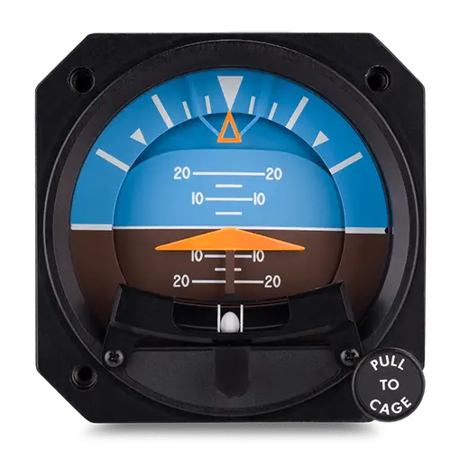
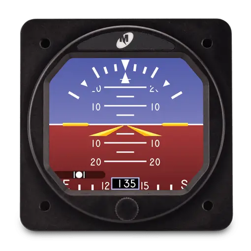
1. Attitude Display
- Artificial Horizon: Blue/brown disc showing sky/ground division
- Aircraft Symbol: Fixed or moving icon representing current orientation
- Pitch Scales: Markings in 5°–10° increments for climb/descent angles
2. Flight Director System (FDS)
- Command Bars: V-shaped cues indicating required pitch and roll inputs
- Mode Annunciators: Text labels showing active modes
- Integration Sources: AHRS, GPS, and flight management computers
3. Backup Systems
- Standby ADI: Electrically powered independent instrument
- Battery Backup: Ensures operation during electrical failures

Attitude Director Indicator Functions
1. Enabling Precision Approaches
Displays ILS localizer and glideslope deviations, guiding pilots to runway thresholds during low-visibility landings.
2. Automation Interface
Couples with autopilot for hands-off control while allowing manual follow-up of computed commands.
3. Emergency Situations
Provides immediate attitude recovery cues during spatial disorientation and unexpected weather encounters.
Why the ADI Is Non-Negotiable for Safety
1. Spatial Disorientation Prevention
Crucial for preventing accidents involving spatial disorientation, providing the sole reliable attitude reference in poor visibility.
2. Workload Reduction
Combines multiple instruments into one display, reducing pilot scan time by over 50% during high-workload phases.
3. Error Mitigation
Flight director commands minimize manual calculation errors while allowing cross-checking against raw data.
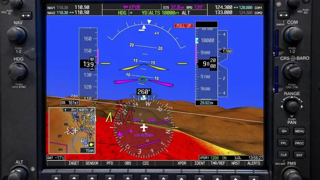
ADI in Modern Glass Cockpits
Primary Flight Displays (PFDs)
Modern glass cockpits integrate ADI functionality into comprehensive Primary Flight Displays that combine attitude, airspeed, altitude, and heading information into a single, intuitive screen.
Standby Systems
Despite digital advancements, separate electromechanical ADIs remain essential for redundancy, often featuring battery-powered operation for total electrical failure scenarios.
The Future of Attitude Director Indicator
1. Predictive Systems
Advanced algorithms that anticipate turbulence and suggest optimal flight trajectories.
2. Augmented Reality Interfaces
Head-up displays that project ADI information directly onto the cockpit windshield.
3. Enhanced Cybersecurity
Protection systems ensuring the integrity of critical flight information.
ADI FAQs
How does an ADI differ from a basic attitude indicator?
The ADI incorporates flight director commands and integrates with navigation systems, while basic attitude indicators only display pitch and bank information.
Can an ADI function after electrical failure?
Standby ADIs typically feature battery backup systems, though operational duration is usually limited to 30-60 minutes.
What causes ADI errors?
Accelerations during takeoff or turns can temporarily affect indicators, though modern solid-state systems minimize these issues.
Is ADI training different for glass cockpits?
Yes, modern training emphasizes automation management and the importance of cross-checking raw data alongside automated systems.


Leave a comment